
fajsdfjash ddsa dsa as sa sad sda sadfjsadjfl jsadjk fjasdlkfjaskdfdklsaj klf
jsadj
asjdklj falsdjf
jaklj

Products
How to Calculate the Heating Capacity Required for a Mold Temperature Controller?
12 November 2026
Author:AODE
share:


A mold that takes too long to reach its operating temperature can delay the entire injection molding schedule. Before choosing a higher-capacity heater, you need to know how much energy the mold requires and how quickly that energy must be delivered.
The heating capacity of a mold temperature controller depends mainly on the mold's mass, material, temperature rise, and required warm-up time. Heat losses and the thermal mass of connected piping and circulating fluid also affect the final equipment selection.
To calculate the theoretical heating capacity, multiply the mold mass by its specific heat capacity and required temperature increase, then divide by the heating time. This gives you a starting point for selecting a temperature control unit (TCU), which can then be adjusted to reflect actual operating conditions.
What Determines the Heating Capacity of a Mold Temperature Controller?
Heating capacity describes how much thermal power a TCU can supply to the process, normally expressed in kilowatts (kW). During startup, the controller heats the circulating medium, which transfers energy through the mold channels into the surrounding metal.
The amount of energy required is closely related to the mold's mass and material. A heavier mold generally requires more heat to reach the same temperature, while different materials absorb energy at different rates. The required warm-up time determines how quickly the heater must provide that energy.
The PMMDA Guide to Mould Temperature Control identifies mold weight, specific heat capacity, operating temperature, and warm-up requirements as important inputs when calculating heating capacity. These parameters establish the basic thermal demand before equipment specifications are compared.
For example, two steel molds may operate at 80°C but require different heating capacities because one weighs considerably more or must reach operating temperature in less time. Looking only at the target temperature would overlook these differences.
How to Calculate Mold Heating Power?
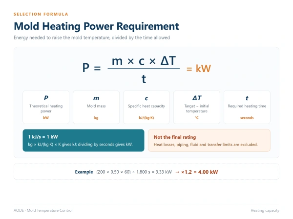
The calculation starts with the heat energy needed to raise the mold temperature. Dividing that energy by the available heating time gives the theoretical average heating power.
Mold Heating Power Formula
P = (m × c × ΔT) / t
| Symbol | Description | Unit |
|---|---|---|
| P | Theoretical heating power | kW |
| m | Mold mass | kg |
| c | Specific heat capacity of the mold material | kJ/(kg·K) |
| ΔT | Target temperature − initial temperature | °C |
| t | Required heating time | Seconds |
With these units, multiplying mass, specific heat, and temperature rise gives energy in kilojoules. Dividing by seconds produces kJ/s, equivalent to kW.
This simplified formula calculates the average power required to heat the assumed mold mass. It does not include environmental heat losses, other components that must be heated, or limitations in heat transfer through the circulating medium.
Determine the Mold Mass and Material
Start with the actual mass of the mold. Engineering drawings or production records are generally more reliable than estimating weight from external dimensions, particularly when the mold contains large internal cavities, inserts, or additional structural components.
The material's specific heat capacity is also required. For preliminary calculations involving steel molds, a value of approximately 0.50 kJ/(kg·K) can be used as an engineering assumption. Actual values vary with material composition and temperature, so detailed calculations should use the appropriate material data.
Set the Temperature Rise and Heating Time
The temperature rise is the difference between the mold's initial and target temperatures. Heating a mold from 20°C to 80°C, for instance, requires a 60°C increase.
You also need to define when the mold should reach that temperature. A production line allowing one hour for preheating has a different power requirement from a line that needs the same mold ready in 15 minutes.
Both parameters should be established before comparing heater ratings. Otherwise, the selected capacity may not match the actual startup schedule.
Heating Capacity Calculation Example for an Injection Mold
Consider a hypothetical 200 kg steel injection mold that must be heated from 20°C to 80°C within 30 minutes. We will use an assumed specific heat capacity of 0.50 kJ/(kg·K) to demonstrate the calculation.
These figures are illustrative engineering inputs rather than measured data from an AODE customer installation.
| Parameter | Value |
|---|---|
| Mold mass | 200 kg |
| Mold material | Steel |
| Specific heat capacity | 0.50 kJ/(kg·K) |
| Initial temperature | 20°C |
| Target temperature | 80°C |
| Temperature rise | 60°C |
| Heating time | 30 minutes (1,800 seconds) |
Calculation
P = (200 × 0.50 × 60) / 1,800
P = 3.33 kW
The mold requires approximately 3.33 kW of theoretical average heating power to achieve the specified temperature increase within 30 minutes under ideal conditions.
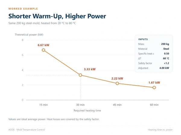
Heating time makes a substantial difference to this result. Keeping the mold mass and temperature rise unchanged gives the following estimates.
| Required Heating Time | Theoretical Heating Power |
|---|---|
| 15 minutes | 6.67 kW |
| 30 minutes | 3.33 kW |
| 45 minutes | 2.22 kW |
| 60 minutes | 1.67 kW |
The same 200 kg mold requires approximately 6.67 kW for a 15-minute warm-up, compared with 3.33 kW for 30 minutes. These values represent ideal average heating power, not guaranteed startup performance.
Advantage Engineering's technical guidance on heat load calculation uses the same underlying relationship between mold thermal load and required heating time. It also explains why shorter warm-up periods require higher heater ratings.
How Do Heat Losses Affect Actual Heating Requirements?
The theoretical calculation assumes that the supplied energy heats only the mold. In practice, the circulation system also contains water or thermal oil, pipes, fittings, and other components that absorb heat during startup.
Energy is lost to the surrounding environment as the mold and connected equipment warm up. The amount depends on operating temperature, exposed surface area, insulation, piping layout, and ambient conditions.
The PMMDA guide recommends a preliminary safety factor of at least 1.2 to account for heat losses. Using that factor with the previous calculation gives:
Adjusted Heating Power
P_adjusted = P × Safety Factor
P_adjusted = 3.33 × 1.2
P_adjusted ≈ 4.00 kW
The adjusted result is approximately 4.00 kW. This is an initial estimate rather than a fixed specification for a 200 kg mold.
The 1.2 factor accounts for an allowance in the preliminary calculation, but it does not automatically describe every additional thermal load in the connected system. Large piping networks, unusual operating temperatures, or demanding startup conditions may require a more detailed assessment.
When reviewing a heating requirement, we distinguish the energy needed to warm the mold from the heater capacity available at the TCU. The final selection must also reflect how effectively that heat reaches the mold within the required time.
How to Choose a Mold Temperature Controller Based on Heating Capacity?
Once the heating requirement has been calculated, you can compare it with the capacities available in standard temperature control units.
For the hypothetical mold above, the adjusted estimate is approximately 4.00 kW. A standard 6 kW heater could be considered as a starting point, provided the controller also meets the process temperature and circulation requirements.
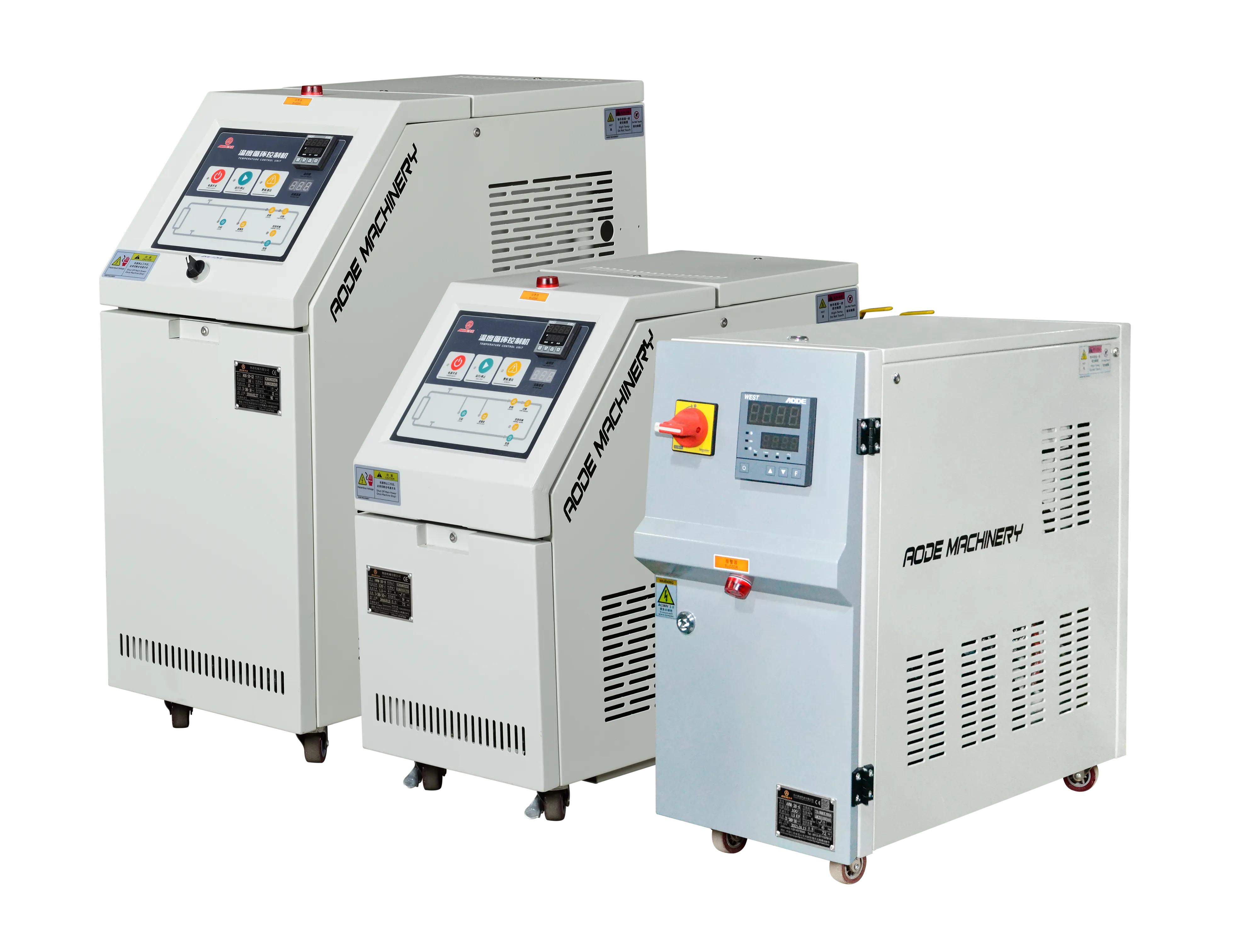
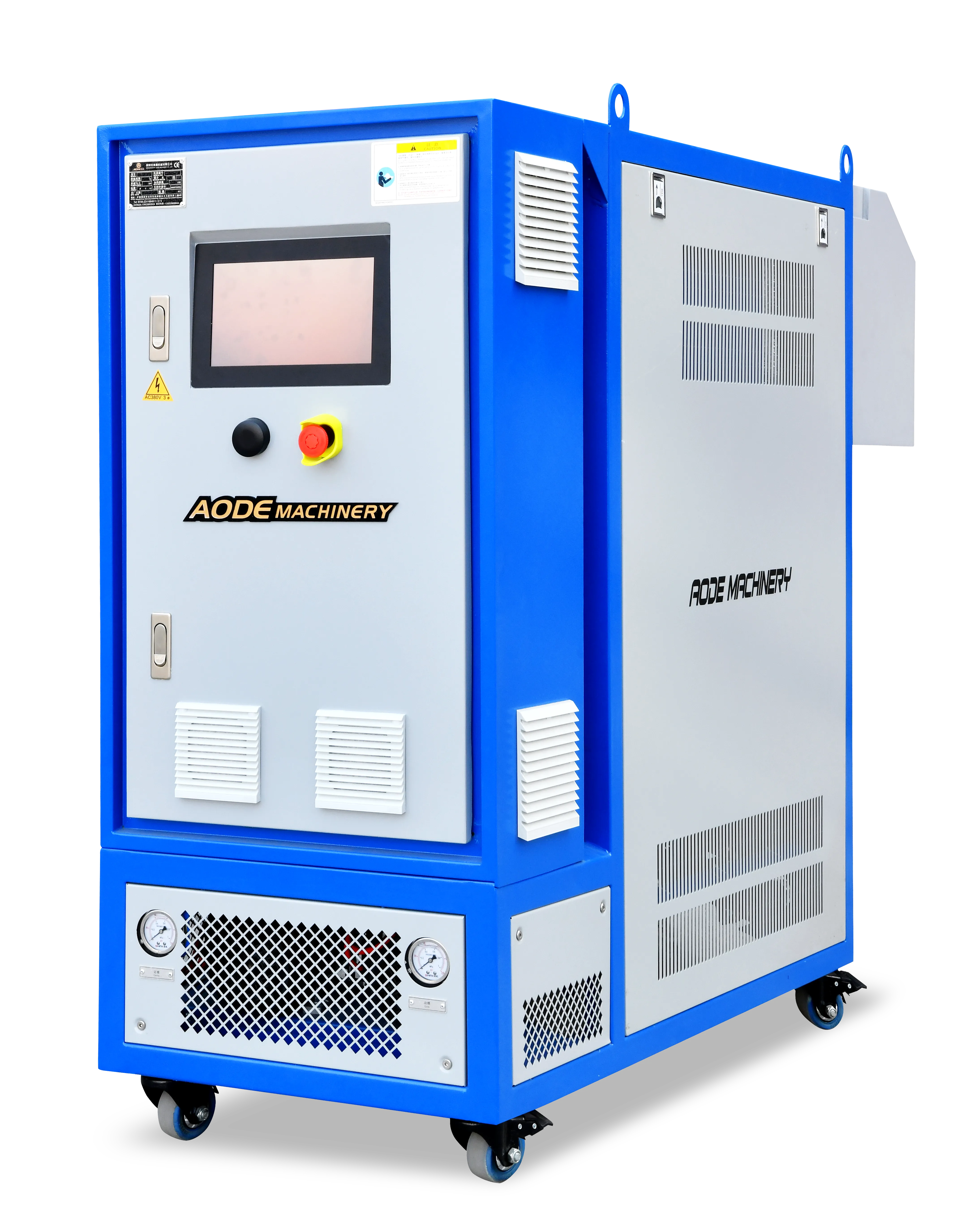
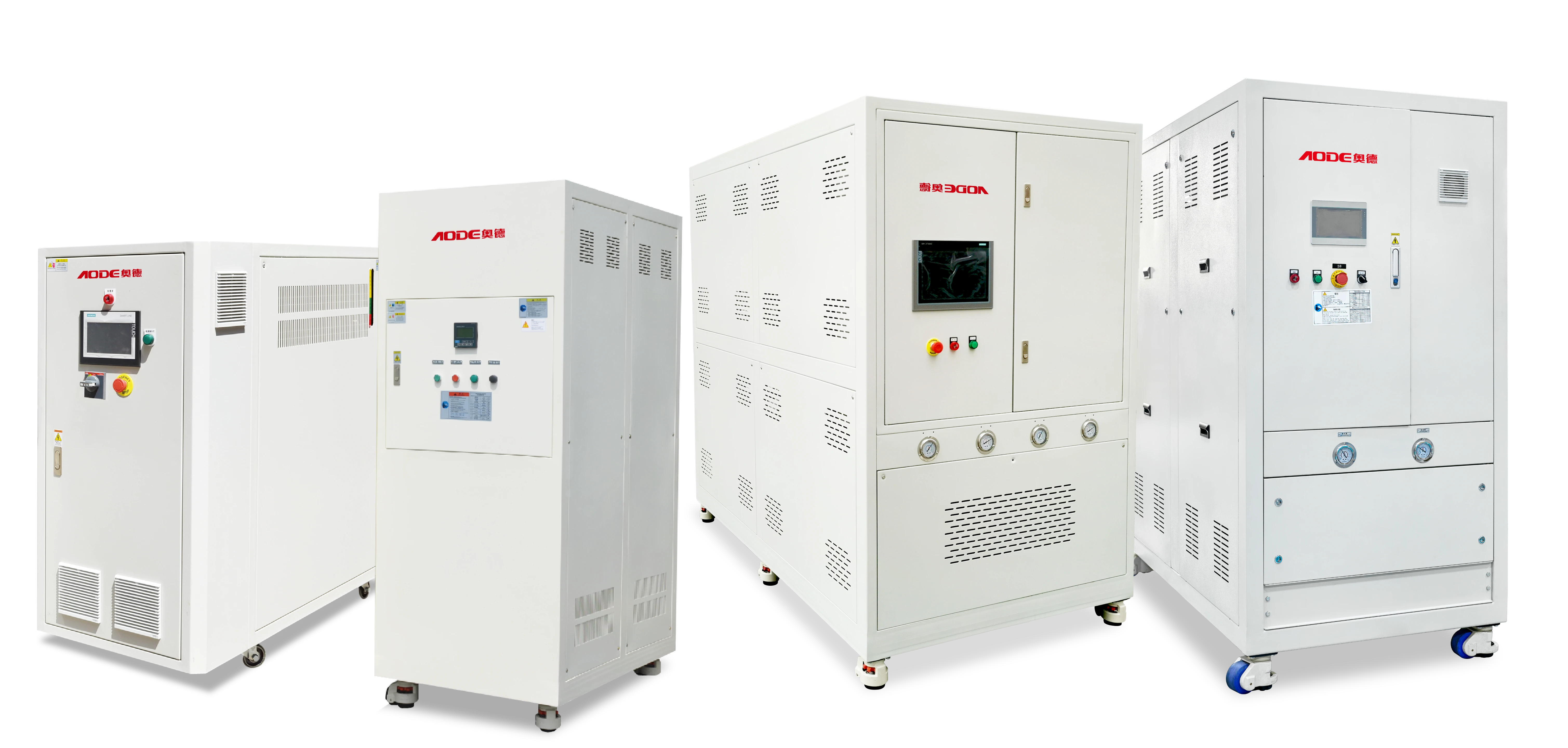
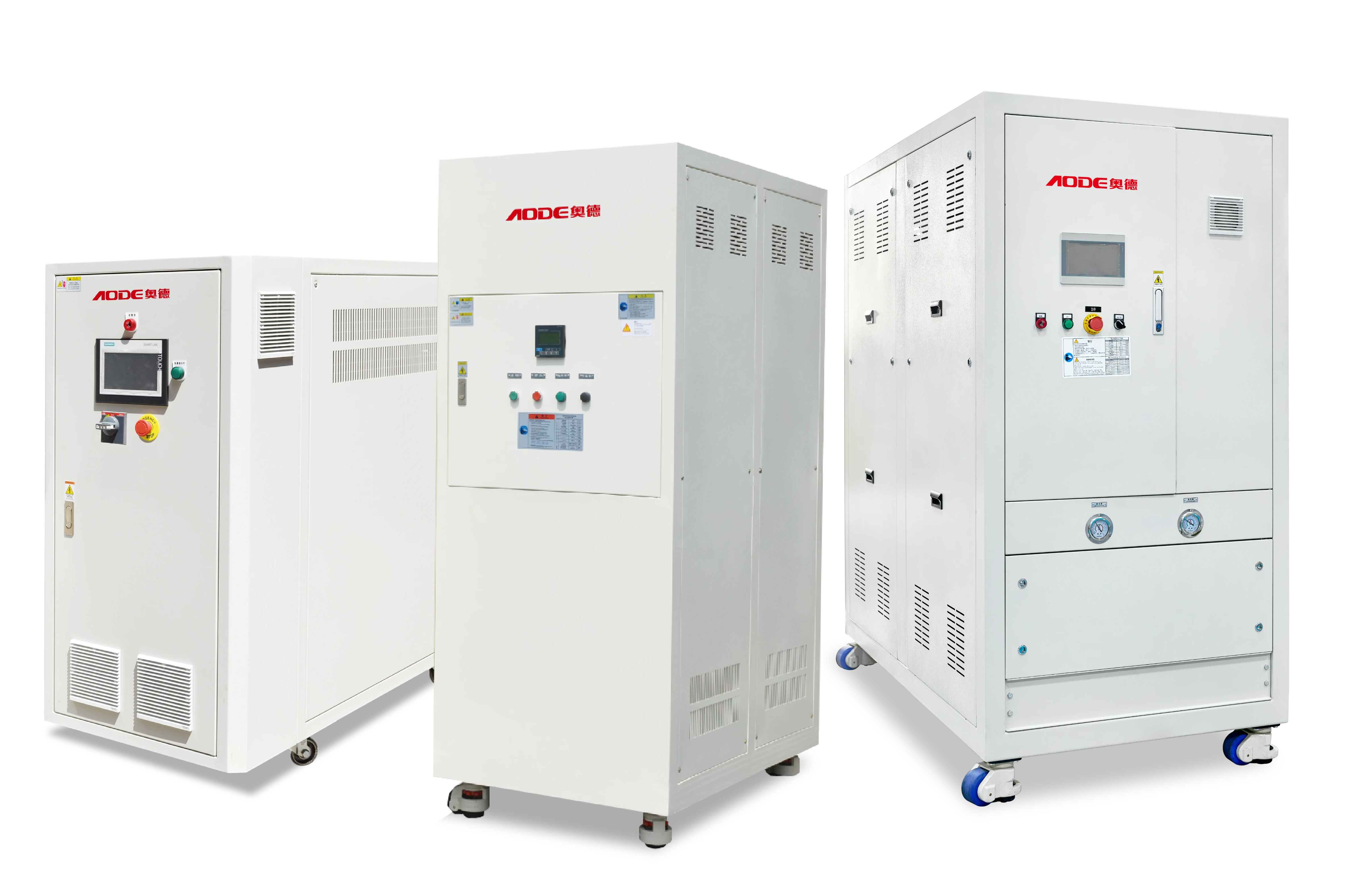
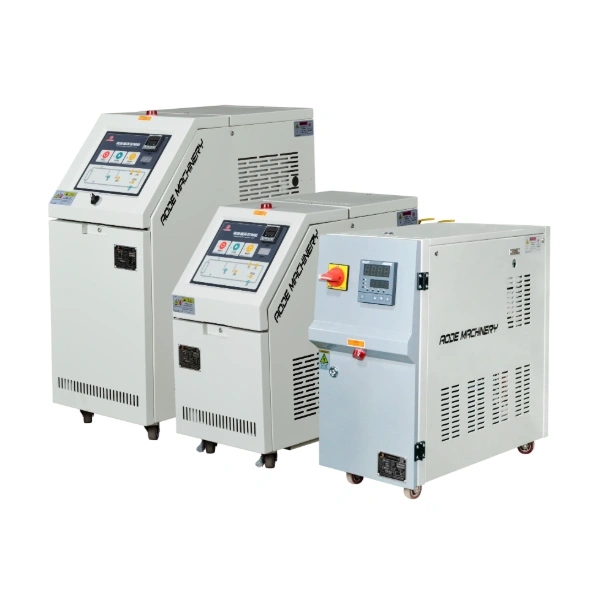
AODE's Standard Water Temperature Controller series provides several heating and pump configurations for injection molding applications.
| AODE Model | Heating Capacity | Rated Pump Flow | Pump Head |
|---|---|---|---|
| AWM-05(A) | 6 kW | 26 L/min | 15 m |
| AWM-10(A) | 9 kW | 100/33 L/min | 16/20 m |
| AWM-20 | 12 kW | 150 L/min | 18 m |
| AWMD-10 | 9 + 9 kW | 100 + 100 L/min | 16 m |
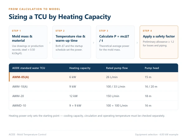
Source: AODE Standard Water Temperature Controller specifications. The values represent listed equipment configurations. Actual circulation flow depends on the connected system and pump operating conditions.
For a calculated requirement of approximately 4.00 kW, the AWM-05(A)'s 6 kW heating capacity provides a useful reference for initial equipment evaluation. Whether that model can achieve the required warm-up time must still be confirmed using the actual mold and circulation conditions.
A larger heater is not automatically the better choice. If the circulation system cannot transfer heat efficiently, increasing heater capacity may have a limited effect on the mold's heating rate.
The AWM series also illustrates why heating power and pump performance need to be evaluated together. AODE offers different standard configurations, with options for customizing heating power and pump specifications when a project requires a different combination.
AODE Water Temperature Controller for Light Guide Plate Injection Molding
The importance of matching temperature control equipment to actual process conditions can also be seen in AODE's light guide plate injection molding application.
Light guide plates require consistent molding conditions because surface quality and dimensional variation can affect their optical performance. In the published project, the temperature control requirements extended beyond the heater rating to include temperature regulation, heating system construction, and reliable circulation.
AODE's solution used a water temperature control system with a water-electricity separation heating design and an integrated welded piping structure. According to the published case, these design choices addressed concerns related to heater scaling, sealing reliability, and maintenance in precision injection molding.
The project also reports improvements in product quality and production performance after implementation. However, the published information does not include mold weight, rated heating capacity, measured warm-up time, or quantified energy savings.
For this reason, the case should not be used to validate the 200 kg calculation presented earlier. Its value lies in showing how actual equipment selection must also address process-specific requirements that cannot be determined from heating power alone.
For an application like this, the calculated thermal load helps establish the heater requirement, while the mold's operating temperature, circulation conditions, and reliability expectations guide the remaining equipment configuration.
What Other Factors Affect TCU Sizing?
After determining the heating requirement, three additional specifications deserve attention: circulation performance, cooling capacity, and operating temperature.
Circulation flow and pump performance determine how effectively heated water or oil moves through the mold. The pump must provide sufficient flow at the pressure required by the connected circuit. Narrow channels, long pipelines, and multiple fittings can increase resistance and reduce actual flow.
Cooling capacity becomes important once injection molding production begins. The molten material transfers heat into the mold during each cycle, and the temperature control system may need to remove that energy to maintain the operating temperature. Heating and cooling requirements should therefore be assessed separately.
Operating temperature and heat transfer medium influence whether a water-based or oil-based controller is appropriate. AODE provides Water Temperature Control Units and Oil Temperature Control Units for different processing conditions.
The combination of these specifications determines whether a controller can meet both startup and continuous production requirements. Heating power provides the initial sizing reference, while circulation, cooling, and operating temperature complete the equipment assessment.
Frequently Asked Questions
How Do You Calculate the Heating Capacity of a Mold Temperature Controller?
Calculate the theoretical heating power by multiplying mold mass by specific heat capacity and the required temperature rise, then dividing by heating time in seconds. With mass in kg and specific heat in kJ/(kg·K), the result is in kW. The calculated value should then be assessed against relevant heat losses and additional system thermal loads before selecting a TCU.
How Much Heating Power Does a 200 kg Injection Mold Need?
The required power depends on the mold material, temperature rise, and warm-up time. For the example in this article, heating a 200 kg steel mold from 20°C to 80°C in 30 minutes requires approximately 3.33 kW theoretically. Applying an illustrative 1.2 safety factor increases the estimate to approximately 4.00 kW, although actual installation conditions may change the requirement.
Does a Larger Mold Require a More Powerful Heater?
A heavier mold normally requires more energy to reach the same target temperature, but heater power also depends on how quickly the temperature increase must be achieved. A large mold with a longer preheating period may require less average heating power than a smaller mold with a demanding startup schedule. Material properties and thermal losses also affect the calculation.
Does Higher Heating Capacity Mean Faster Mold Heating?
Higher heating capacity can shorten warm-up time when available heater power is the limiting factor. However, actual heating performance also depends on circulation flow, heat transfer through the mold channels, and thermal losses. If heat cannot be delivered effectively to the mold, increasing heater capacity alone may not provide the expected reduction in startup time.
Is Heating Capacity the Same as Cooling Capacity in a TCU?
No. Heating capacity describes the rate at which a TCU can supply thermal energy, while cooling capacity describes how much heat it can remove under specified conditions. An injection mold may need substantial heating during startup and continuous cooling during production. Both values should be checked separately because a higher heater rating does not necessarily provide greater cooling performance.
Conclusion
A reliable heating capacity calculation gives you a starting point for mold temperature controller selection, not a complete equipment specification. The calculated power must be checked against the real heating load, warm-up requirements, and available TCU configurations.
Share your mold weight, target temperature and warm-up time with our engineers — contact AODE to confirm a suitable heating capacity and pump configuration.
References
PMMDA. Guide to Mould Temperature Control. Polymer Machinery Manufacturers and Distributors Association. https://www.pmmda.org.uk/wp-content/uploads/2024/01/Guide-to-Mould-Temperature-Control.pdf
Advantage Engineering. Heat Load Calculation for Mold Temperature Control Units. Technical Information FYI #142. https://www.advantageengineering.com/fyi/142/advantageFYI142.php
AODE. Standard Water Temperature Controller — Product Specifications. https://www.mouldtcu.com/product/standard-water-temperature-controller.html
AODE. Water Temperature Controller for Light Guide Plate Injection Molding — Application Case. https://www.mouldtcu.com/case/technical-article-light-guide-plate-injection-molding-water-tcu.html
 Back to List
Table of Contents
×
CONTACT US
Cookie Policy
We use cookies and other tracking technologies online. Please read our Cookie Policy, which is part of this Cookie Policy , and is incorporated herein by reference.

loading...